
 |
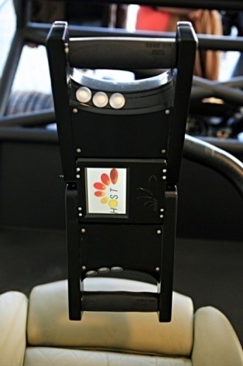
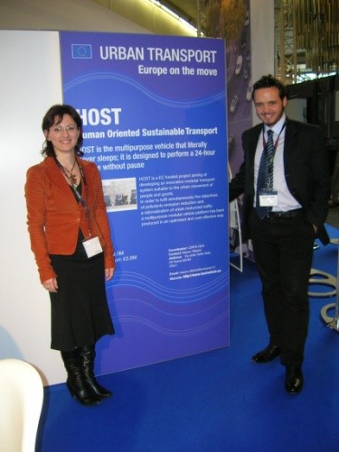
HOST PROJECT |
About HOST
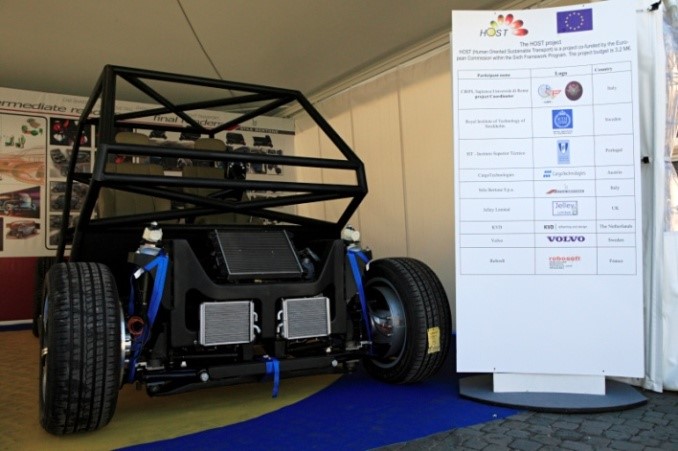
The Host (Human Oriented Sustainable Transport) vehicle’s prototype is the result of a 3,2-million-euro project (funded by the European Commission within the 7th Framework Program) on which a Consortium, coordinated by CIRPS – Centro Interuniversitario di Ricerca Per lo Sviluppo sostenibile, and composed by 9 European partners from 7 EU Countries, has been working since 2007. From 2016 the HOST prototype remained within CIRPS for further tests and various technological and application developments, by means of several European, national, and regional Italian programs (POLOIDROGENO Regione Lazio; TEPSI; UNIfHY; PlanGridEV; UNIPOWER), still continuing today. The newest entries are: 3eMOTION www.3emotion.eu (2015-2022);BLAZE www.blazeproject.eu (2019-2022); GICO https://cordis.europa.eu/project/id/101006656/it. (2020-2024); TRUST https://trustproject.eu/public/ (2020-2023).
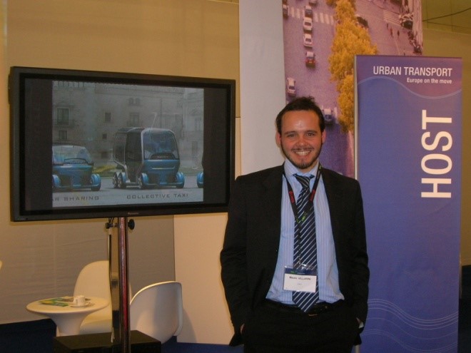
HOST is a vehicle that never sleeps. It was designed to perform various services, as school bus, urban goods delivery, collective taxi, and garbage collection. A 24-hour service, without pause.
 |
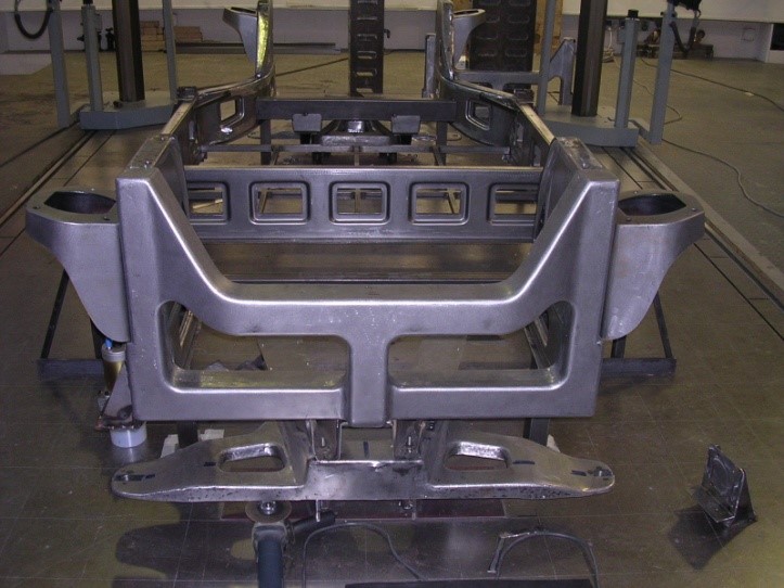
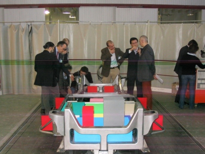
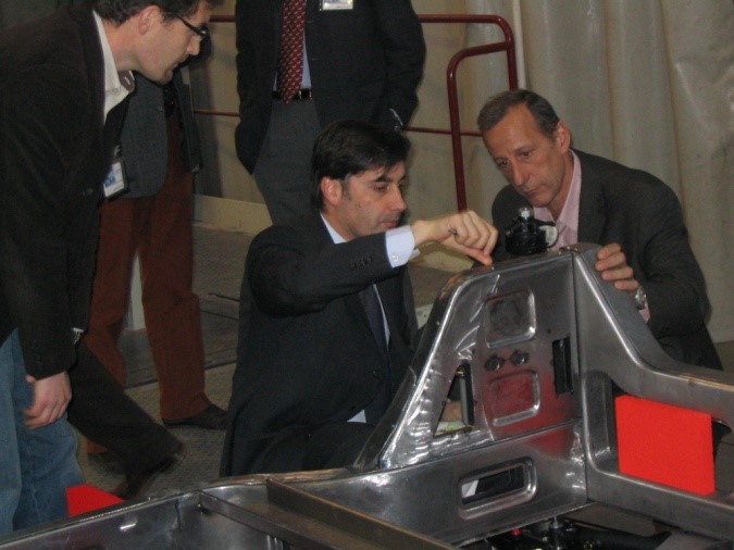
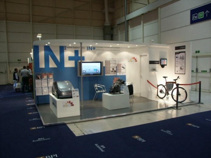
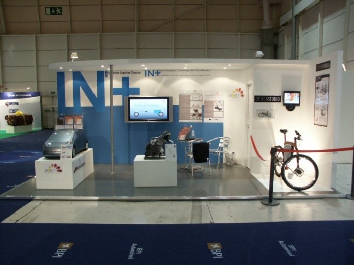
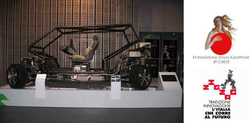
History and evolution The idea started with a national project that proposed for the first time the idea of a “motorized platform” with electric motors integrated in the wheels and the possibility of maneuvering in rotation and translation. From 2008 HOST was financed by the European Commission. The Project had 9 international partners coordinated by CIRPS. The prototype was presented at the “Innovation Cube” area of the Bologna Motor Show, Which was fully covered by national media and press. |
Strategic objective: creation of a spin-off company
HOST has been exhibited as Italian technological excellence at the Museum of Science of the Future “Miraikan” in Tokyo. Now it must generate entrepreneurial activity in Italy, as a university spin-off.
First of all HOST is a new concept of sustainable mobility, conceived for the transport of people and goods.
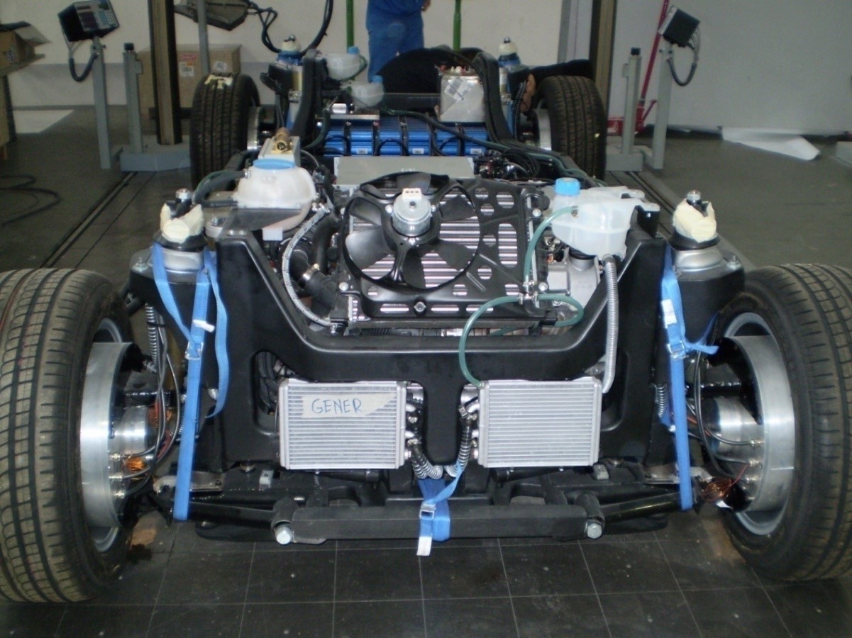
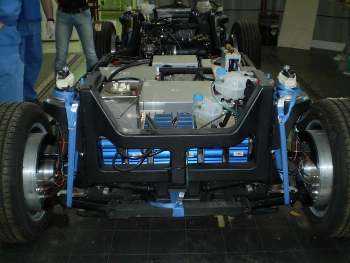
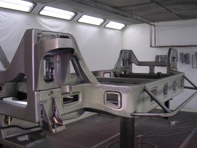
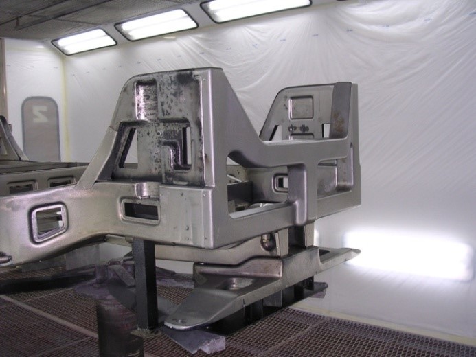
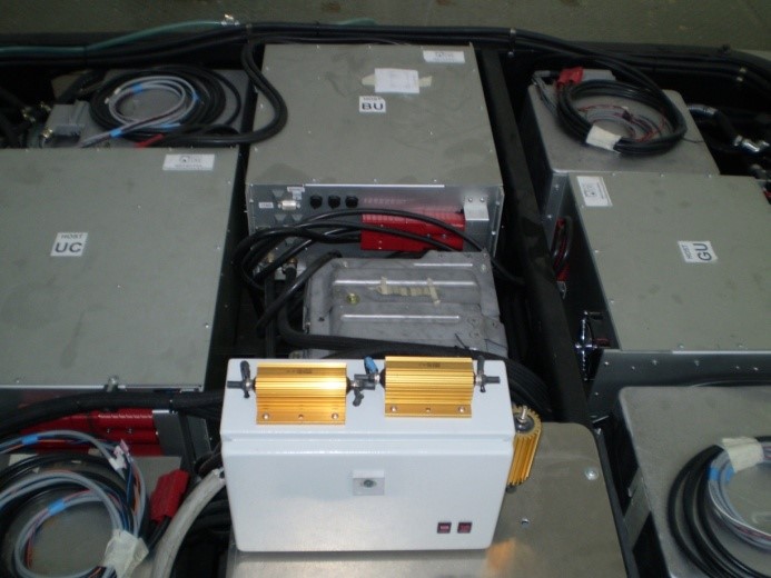
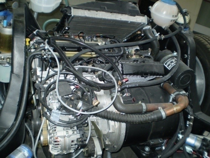
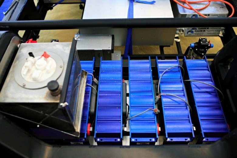
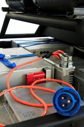
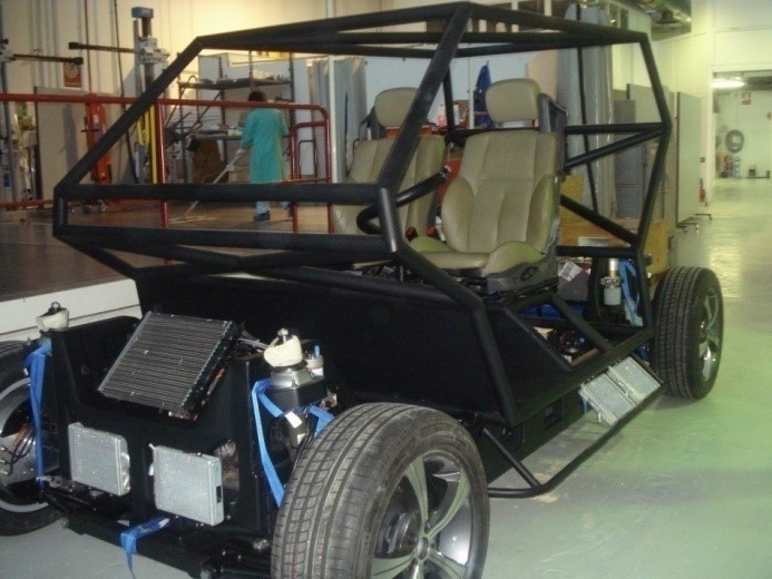
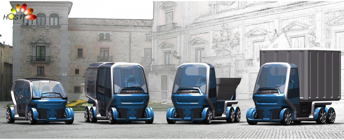
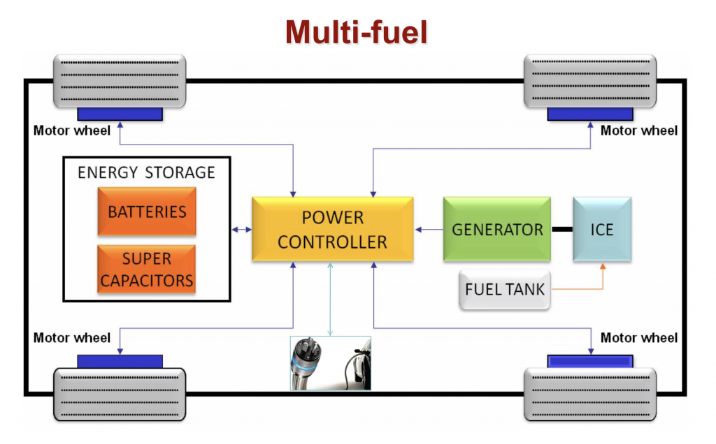
It is based on the modularity and re-using concepts. Modularity of suspensions and chassis, so it can be converted from a city car into a van; modularity of the powertrain, different energy system modes consisting of a series hybrid (Diesel-electric) provided with a plug-in function, which enables the vehicle to be recharged using the electricity from the grid.
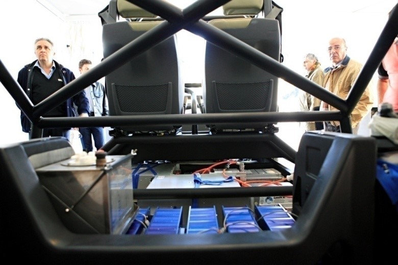
Alternatively, Host can house a hydrogen fuel cell and is equipped with a energy storage system easily adaptable to a wide range of powers. The result is a vehicle that increases transport opportunities and that, being able to work 24 hours a day, cuts down the costs deriving from its complexity.
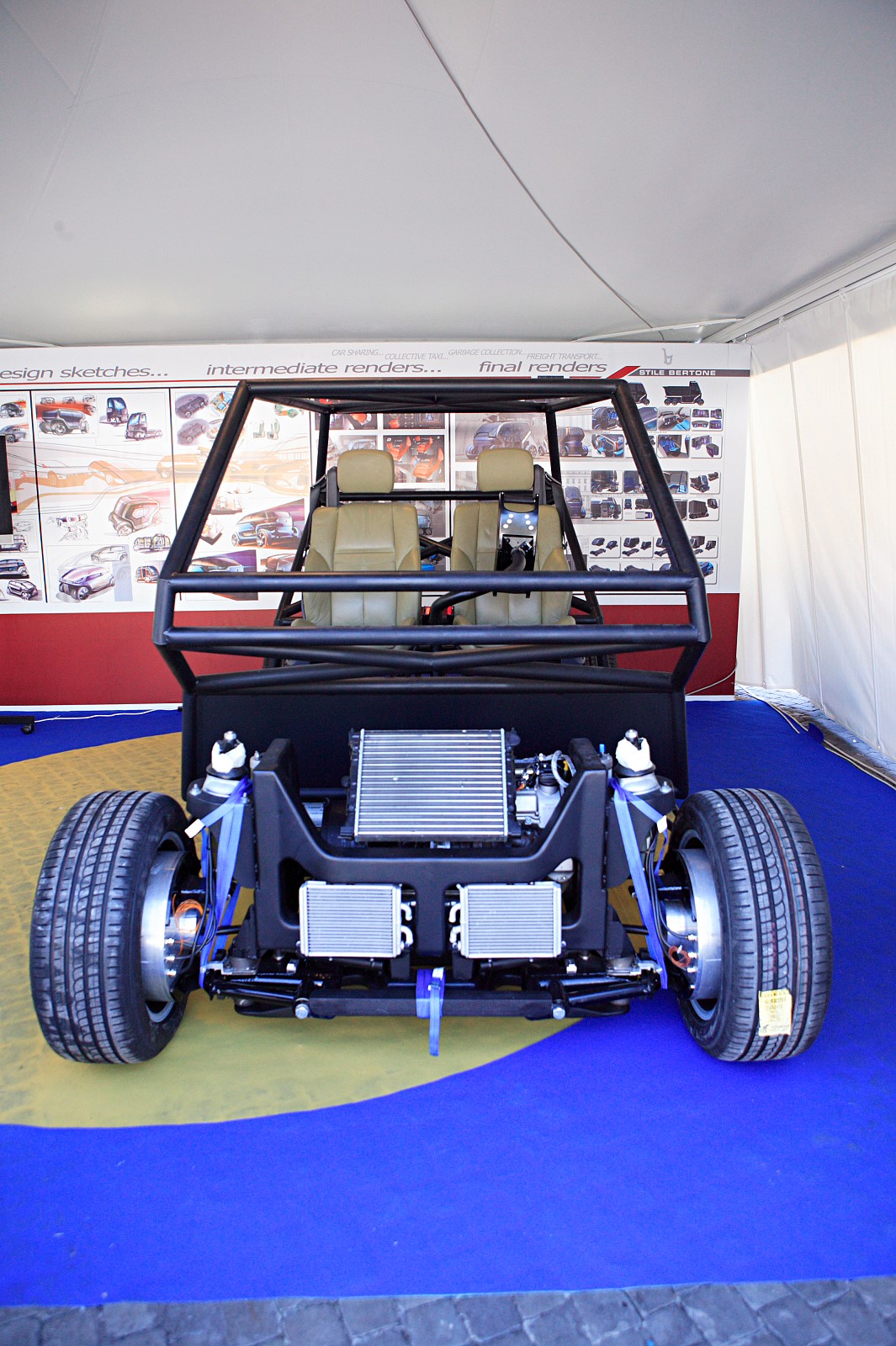
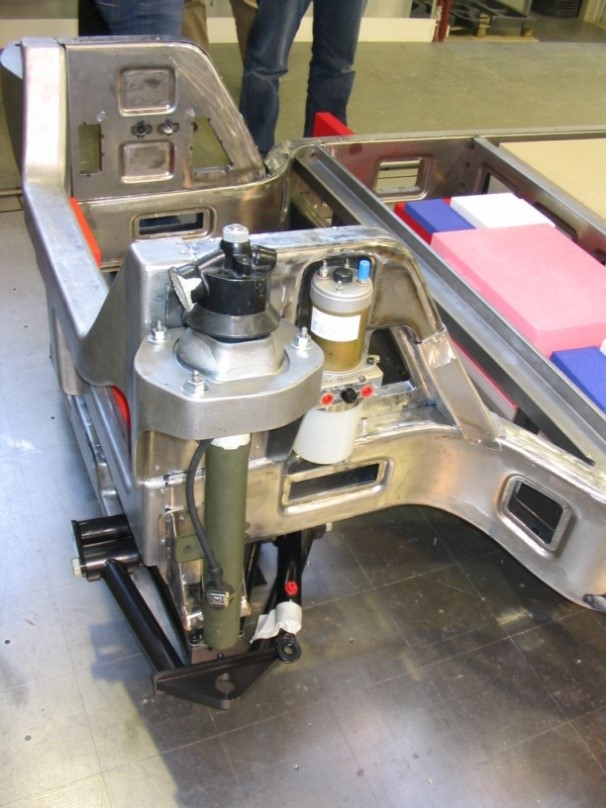
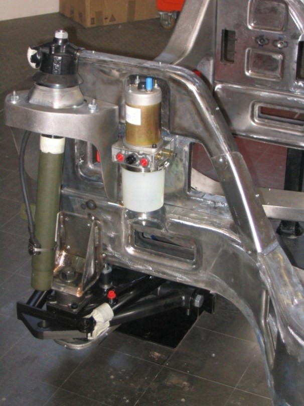
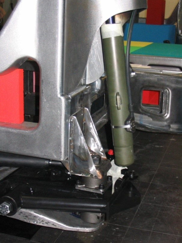
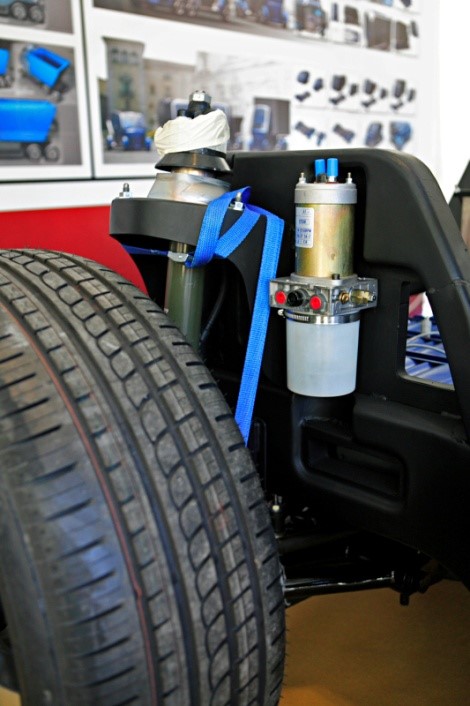
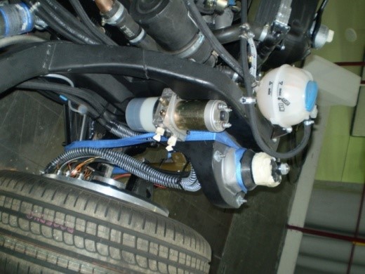
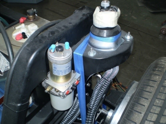
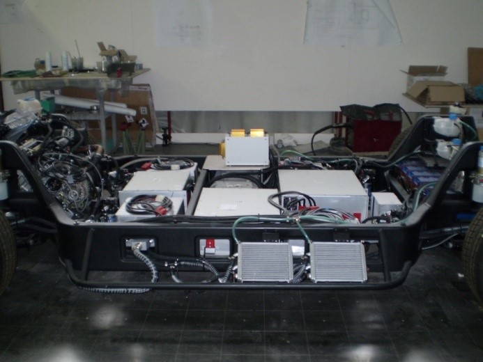
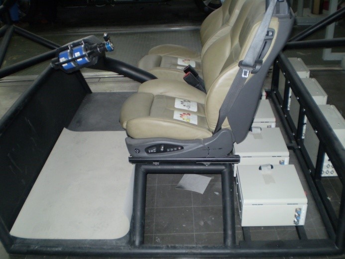
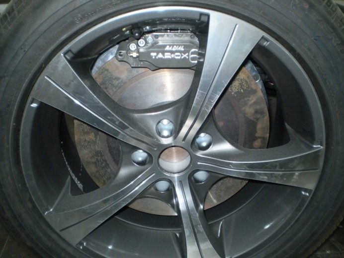
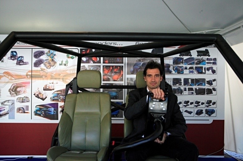
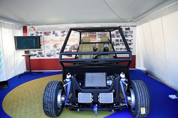
Thanks to an electric motor per each wheel and to a drive-by-wire architecture, HOST hasn’t any mechanical link between the chassis and the bodywork. Thus, the vehicle’s cabin can be changed according to the service required by an innovative onboard horizontal transhipment system and can turn on itself and translate.
This new concept is ideal for urban mobility and offers great advantages for the transport logistics flows of goods and people, decreasing the number of vehicles circulating in towns.
Key features:
- It has a single platform for a modular multi-purpose urban vehicle, which can be configured, in a very short time (minutes), as a collective taxi or car sharing vehicle, as a school bus, a light goods distributor or light waste collector;
- Minimized dimensions allow mobility even in urban streets with a narrow track;
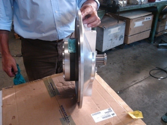
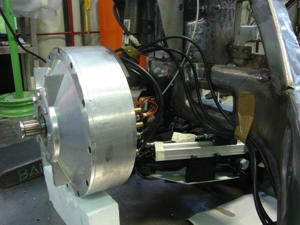
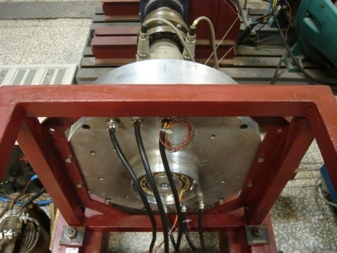
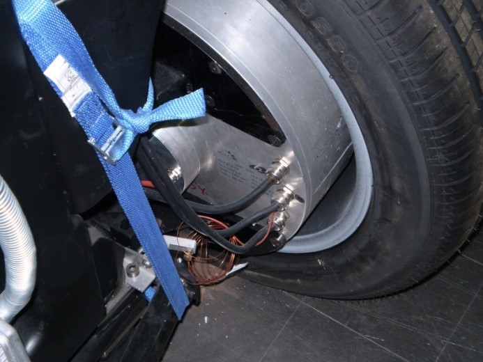
- Maximum mobility thanks to the possibility of rotating the 4 (independent) wheels (the wheels each contain an independent electric motor, for traction and rotation, which reduces the overall dimensions of the vehicle significantly;
- It can be a zero-emission vehicle with a completely “clean” operating cycle, in its configuration with “green” fuel cells and hydrogen;
- “Full drive by wire solution” commands.
HOST prototype is going to be developed in its second generation version, looking at the industrial application.
→HOST Projects-e-ELECTRIC-BUS-WITH-SELF-PRODUCED-ENERGY
Watch the video
|
|
|
|
|
|
|
|
|
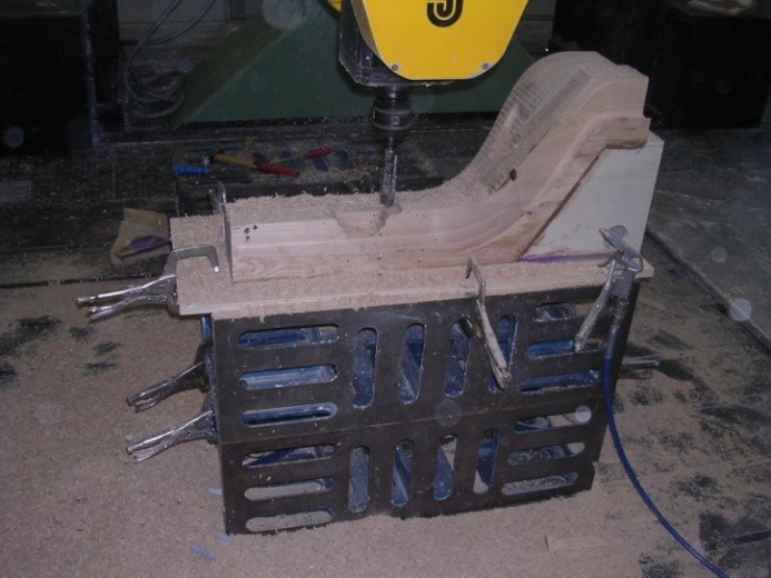
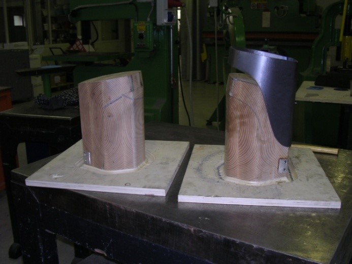
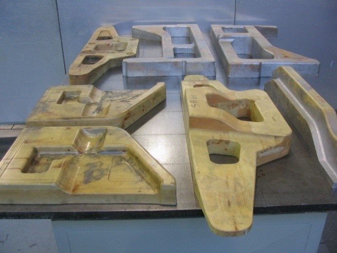
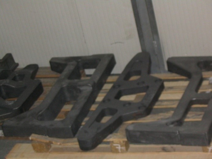
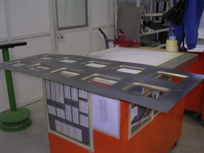
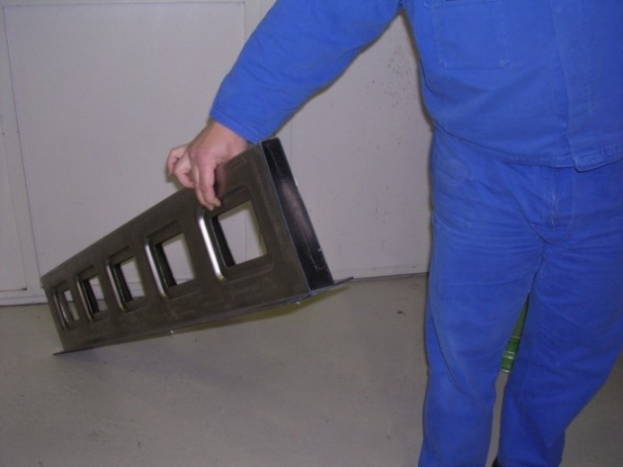
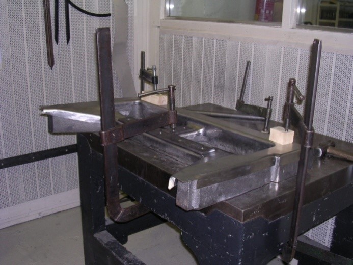
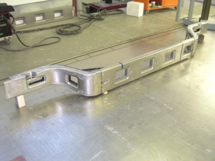
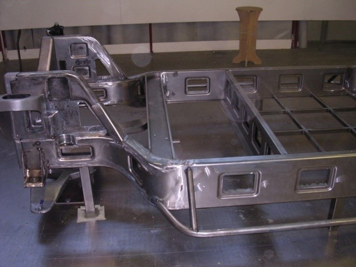
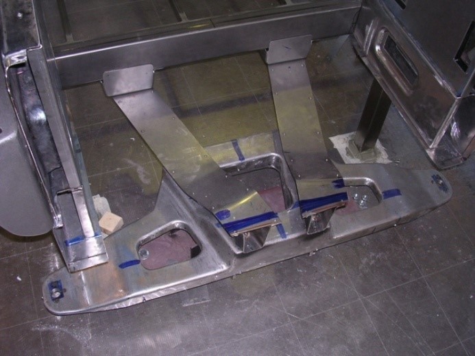
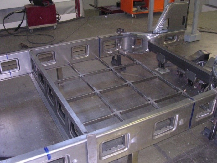
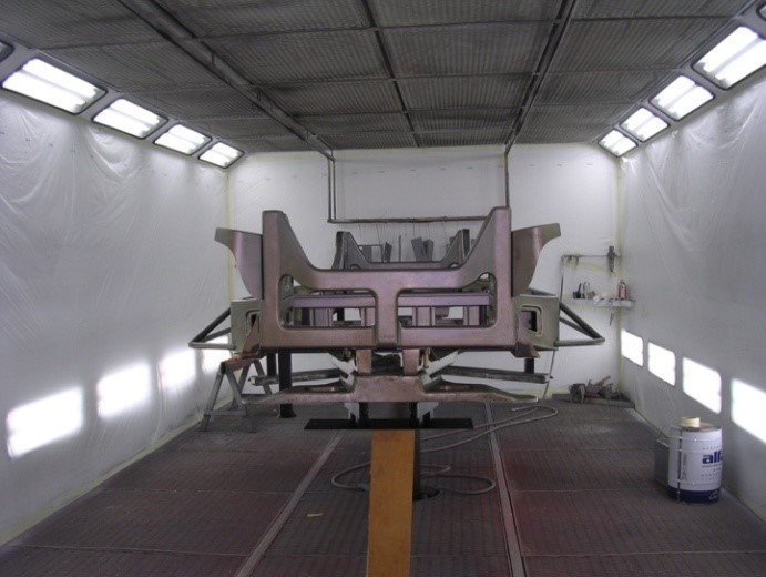
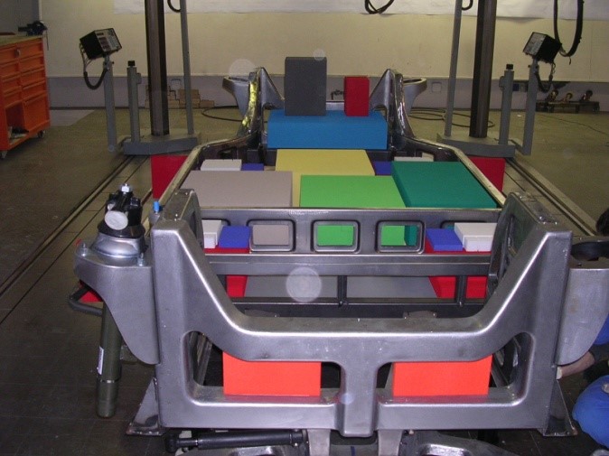
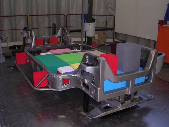
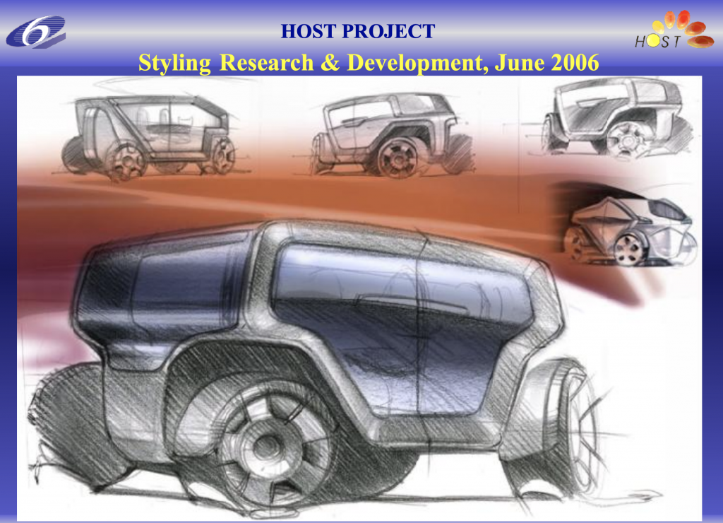
→HOST – Styling Research Progress on the job
|
The prototype at H2 Roma Event
|